点击: 作者:loveplc
为了在CPU诊断缓存的纯文本内写入用户指定消息必须进行:
1.) 在STEP 7中配置消息。
2.) 写入诊断缓存所需的事件ID。

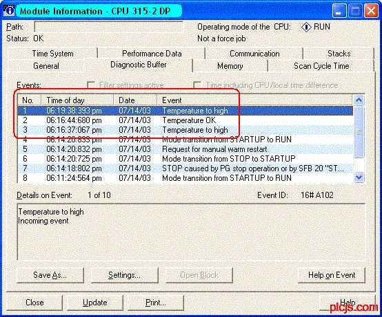
图1:有用户指定消息文本的诊断缓存
该条目描述了在STEP 7中如何配置一个消息文本,如何将相关事件ID结构化及如何写入到有SFC 52“WR_USMSG”的诊断缓存。
附件实例程序包括有配置消息的STEP 7项目,程序块在诊断缓存内根据输入值写入相关事件ID。
注意事项:
条目ID 15166942描述了如何使用系统函数“WR_USMSG” (SFC 52) 写入用户指定事件,该事件包括诊断缓存的任何附加信息。在该条目中有一个功能块调用SFC 52以便只用需要的基本数据块。
在相关的实例程序中直接调用SFC 52,因为在这种情况下仅需要事件ID。其它附加信息不需要。消息文本用STEP 7组态并保存到程序中.
组态一个用户指定消息STEP 7
首先打开消息组态对话框。选择项目树中的“S7 Program”目录然后通过弹出菜单 (右击)打开消息配置窗口“特殊对象属性”->“消息...”。
按“新消息”按钮出现一个条目显示新消息从而可做相应的修改。

图 2:消息配置窗口
在该例中配置下列消息:
|
窗口 WWW_PLCJ-S_COM-PLC-技.术_网(可-编程控-制器技术-门户) |
输入 (德语) WWcW_PLCJS_COM-PLC-技.术_网 |
|
消息指示符 WWW_PLCJS@_COM%-PLC-技.术_网 |
WR_USMSG(1) (默认) P_L_C_技_术_网——可——编——程——控-制-器-技——术——门——户 |
|
错误类别 WWW_P※LCJS_CO※M-PLC-技-.术_网 |
A (默认) WWW_PLCJS_COM-PLC-技.术_网 |
|
消息号 WWW_PLC※JS_COM-PLC-技.术_网(可编程控※制器技术门户) |
2 P.L.C.技.术.网——可编程控制器技术门户 |
|
输入的消息文本 WWW_PLCJS※COM-PLC-技×术_网(可编程控※制器技术门户) |
温度太高(由事件是来或去决定)例:A102 WWW_PLC※JS_COM-PmLC-技.术_网 |
|
输出的消息文本 WWW_P※LCJS_CO※M-PLC-技-.术_网 |
温度 OK(由事件是来或去决定)例:A002 WW.W_PLCJS_COM-PLC-技.术_网 |
注意事项:
自定义诊断消息只能显示在PG上不能传送到操作系统。
显示诊断文本需要PG上的STEP 7项目。
使用SIMATIC管理器上的功能:“选项” ->“使用多种语言的文本管理”,可以设置另一种语言 (对消息文本和注释)。附件项目可以使用两种语言(德语/英语)。
事件ID结构
与消息关联的事件ID由下面内容组成:
W#16#<错误类别><输入/输出的消息代码><十六进制中的消息编号>
- 错误类别:A或B (见组态屏蔽)
- 输入/输出的消息代码:输入的消息= 1; 输出消息 =0
- 消息编号:在十六进制格式中的组态屏蔽号
对于组态消息有下列事件 ID:
- W#16#A102 - 输入的消息“温度太高”
- W#16#A002 - 输出的消息“温度 OK”
实例程序描述
此例中,根据温度值,两个消息文本之一“温度OK”或“温度太高”写入S7 CPU的诊断缓存内。
当调用FB 1 (在OB1中)时,数值“100”作为限定值被传送。根据温度,对应MW 20中的数值,在诊断缓存中输入进入或输出消息的事件ID。在项目中定义消息文本。
边缘触发标记确保当超过或低于限定值时只在诊断缓存中写入消息一次。
使用变量表可以改变温度和限定值以便在诊断缓存中产生相应的条目。如果在STEP 7中显示诊断缓存内容那么显示文本(“PLC” -> “诊断/设置” ->“模块状态” -> 标签:“诊断缓存”。
7.5 Screen Number Area
Application
The operating units store information concerning the screen currently open on the
unit in the screen number area.
This enables the transfer of data regarding the current operating unit display
content to the PLC which, in turn, can trigger certain reactions; e.g. call in a
different screen.
Condition
If the screen number area should be used, it must be specified in the configuration
as an area pointers. It can only be stored in one PLC and only once.
The screen number area is downloaded to the PLC spontaneously, i.e. the transfer
is always initiated when a change is selected on the operating unit. Therefore, it is
not necessary to configure an acquisition cycle.
Structure
The screen number area is a data area with a fixed length of data words.
The structure of the screen number area in the PLC memory is illustrated below.
7.7 Coordination Area
The coordination area is two data words long. It serves to realize the following
functions:
_ Detection of operating unit startup by the PLC program,
_ Detection of the current operating unit operating mode by the PLC program,
_ Detection by the PLC program that the operating unit is ready to communicate.
Note
Each time the coordination area is updated by the operating unit, the entire
coordination area is written.
Therefore, the PLC program must not execute any modifications in the
coordination area.
In order to use the coordination area, both data words must be specified, whereby
the first data word is used. The second data word is reserved. Figure 7-8 illustrates
the structure of Byte 1 in the first data word.
L
C
技
术
网
|
可
编
程
控
制
器
技
术
门
户
|
十
万
P
L
C
工
程
师
的
共
同
选
择
!