CPU215与CPU315的PROFIBUSDP连接
日期:2010-3-17 19:18:00 点击:
来源:本站整理
作者:
来源:本站整理
作者:
点击【 大 中 小 】放大字体.
QUESTION:
How can I configure a CPU 215-2DP as DP slave?
ANSWER:
This entry describes how to configure a CPU 215-2DP as slave on a CPU 315-2DP as master. STEP 7 V5.x and Micro/WIN 32 V3.x are used for the configuration.
Configuring in STEP 7 V5
1. Create a new project.
2. Add an S7-300 station to the project.
3. Open the hardware editor.
4. Add the power supply and the CPU 315-2DP. For test purposes, under Properties for the CPU configure the Marker Byte 1 as clock marker.
5. Attach the CPU 215-2DP to the DP segment. The CPU215-2DP is located in the hardware catalog under
'PROFIBUS DP \DP VO SLAVE\SIMATIC \ S7-200 CPU 215-2DP'
6. You must add an input/output module to the CPU 215-2DP. In this example a '2 bytes out / 2 bytes in' module is used. The module is located in the hardware catalog under
'...\S7-200 CPU 215-2DP\...'
Mark the CPU 215-2DP. Drag-and-drop the module to the open table.
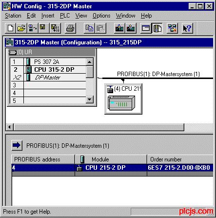
7. Create the addresses for the input and output areas of the slave.
8. Double-click the module and enter the start addresses in the dialog that opens.
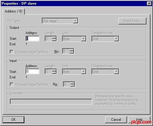
9. Enter the memory area in which the CPU 215-2DP is to store the inputs and outputs.
10. Double-click the CPU 215-2DP. The 'Properties - DP slave' opens.
11. In the 'Parameter Assignment' tab you specify the offset in the V memory of the CPU 215-2DP an. In the example the offset is 5000. This means that the DP inputs are in VB5000 or VB5001 and the DP outputs in VB5002 or VB5003.
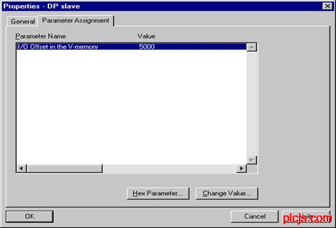
12. Set the bus parameters. In the 'General' tab click the 'PROFIBUS' button. In the dialog that opens go to the 'Network Settings' tab.
Note:
In 'STEP 7 - Micro / WIN' you can only set the transfer rates to a value of 19.2 Kbaud. But the bus system can and must be much higher (up to 12 Mbaud). The CPU then sets itself automatically to this baud rate. This happens regardless of what has been set in 'STEP 7 - Micro / WIN'.
13. Set 19.2 kbaud as transmission rate.
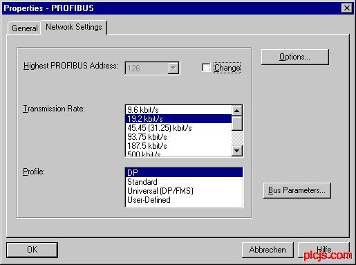
14. Save the hardware configuration.
15. For the test, the clock marker is to be transferred into the output byte 0. This happens, for example, in the OB1 with the following commands
L MB
T AB 0
16. Load the configuration into the CPU 315-2DP
Parameterizing the CPU 215-2DP in Micro/WIN 32
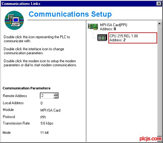
1. Open Micro/WIN 32 and create a new project. Check whether the connection to the CPU 215-2DP is available.
2. If necessary, adapt the CPU type to the hardware you have.
3. Double-click the system block. Assign the parameters for Interface 1 for the PROFIBUS communication.
WWW_PLCJS※COM-PLC-技.术_网(可※编程控※制器技术门户)
QUESTION:
WWW_P※LCJS_CO※M-PLC-技-.术_网
How can I configure a CPU 215-2DP as DP slave?
WWW_P※LCJS_COM-PLC-)技.术_网
ANSWER:
P.L.C.技.术.网——可编程控制器技术门户
This entry describes how to configure a CPU 215-2DP as slave on a CPU 315-2DP as master. STEP 7 V5.x and Micro/WIN 32 V3.x are used for the configuration.
WWW_P※LCJS_CO※M-PLC-技-.术_网
Configuring in STEP 7 V5
WWW_P※LCJS_COM-PLC-)技.术_网
1. Create a new project.
WWW_PLCJS※COM-PLC-技.术_网(可※编程控※制器技术门户)
2. Add an S7-300 station to the project.
plcjs.技.术_网
3. Open the hardware editor.
WWW_PLCJS_COM-PLC-技.术_网
4. Add the power supply and the CPU 315-2DP. For test purposes, under Properties for the CPU configure the Marker Byte 1 as clock marker.
WWW_PLCJS_COM-PLC-技.术_网
5. Attach the CPU 215-2DP to the DP segment. The CPU215-2DP is located in the hardware catalog under
W1WW_P4LCJS_COM-PLC-技.术_网
'PROFIBUS DP \DP VO SLAVE\SIMATIC \ S7-200 CPU 215-2DP'
WW.W_PLCJS_COM-PLC-技.术_网
6. You must add an input/output module to the CPU 215-2DP. In this example a '2 bytes out / 2 bytes in' module is used. The module is located in the hardware catalog under
WWW_PLCJS_COM-PLC-技.术_网
'...\S7-200 CPU 215-2DP\...'
WWW.PLCJS.COM——可编程控制器技术门户
Mark the CPU 215-2DP. Drag-and-drop the module to the open table.
WWcW_PLCJS_COM-PLC-技.术_网

WWW_PLCJ-S_COM-PLC-技.术_网(可-编程控-制器技术-门户)
7. Create the addresses for the input and output areas of the slave.
WWW_PLC※JS_COM-PmLC-技.术_网
8. Double-click the module and enter the start addresses in the dialog that opens.
WWW_PLCJ-S_COM-PLC-技.术_网(可-编程控-制器技术-门户)

WWW_PL※CJS_COM-PLC-技.术_网
9. Enter the memory area in which the CPU 215-2DP is to store the inputs and outputs.
W1WW_P4LCJS_COM-PLC-技.术_网
10. Double-click the CPU 215-2DP. The 'Properties - DP slave' opens.
P.L.C.技.术.网——可编程控制器技术门户
11. In the 'Parameter Assignment' tab you specify the offset in the V memory of the CPU 215-2DP an. In the example the offset is 5000. This means that the DP inputs are in VB5000 or VB5001 and the DP outputs in VB5002 or VB5003.
WWW_PLCJS_COM-PLC-技.术_网

WWW_PLCJ-S_COM-PLC-技.术_网(可-编程控-制器技术-门户)
12. Set the bus parameters. In the 'General' tab click the 'PROFIBUS' button. In the dialog that opens go to the 'Network Settings' tab.
WWW_P※LCJS_COM-PLC-)技.术_网
Note:
WWW_PLCJS※COM-PLC-技×术_网(可编程控※制器技术门户)
In 'STEP 7 - Micro / WIN' you can only set the transfer rates to a value of 19.2 Kbaud. But the bus system can and must be much higher (up to 12 Mbaud). The CPU then sets itself automatically to this baud rate. This happens regardless of what has been set in 'STEP 7 - Micro / WIN'.
WWW_PLCJS※COM-PLC-技.术_网(可※编程控※制器技术门户)
13. Set 19.2 kbaud as transmission rate.
WW.W_PLC※JS_C,OM-PL,C-技.术_网

WWW_PLCJS_COM-PLC-技.术_网
14. Save the hardware configuration.
WWW.PLCJS.COM——可编程控制器技术门户
15. For the test, the clock marker is to be transferred into the output byte 0. This happens, for example, in the OB1 with the following commands
WWW_PLC※JS_COM-PmLC-技.术_网
WW.W_PLCJS_COM-PLC-技.术_网
T AB 0
W1WW_P4LCJS_COM-PLC-技.术_网
16. Load the configuration into the CPU 315-2DP
WWW_PLCJS@_COM%-PLC-技.术_网
Parameterizing the CPU 215-2DP in Micro/WIN 32
WWW※PLCJS_COM-PL#C-技.术_网(可编※程控※制器技术门户)
1. Open Micro/WIN 32 and create a new project. Check whether the connection to the CPU 215-2DP is available.
WW.W_PLCJS_COM-PLC-技.术_网

WW.W_PLCJS_COM-PLC-技.术_网
2. If necessary, adapt the CPU type to the hardware you have.
WWcW_PLCJS_COM-PLC-技.术_网
3. Double-click the system block. Assign the parameters for Interface 1 for the PROFIBUS communication.
本新闻共2页,当前在第1页1 2
WWW_PLC※JS_COM-PLC-技.术_网(可编程控※制器技术门户)
评论内容
载入中...
载入中...
P
L
C
技
术
网
|
可
编
程
控
制
器
技
术
门
户
|
十
万
P
L
C
工
程
师
的
共
同
选
择
!
L
C
技
术
网
|
可
编
程
控
制
器
技
术
门
户
|
十
万
P
L
C
工
程
师
的
共
同
选
择
!
·最新招聘信息
·最新求职信息
·推荐产品
·推荐厂商
·栏目热门排行
·站内热门排行